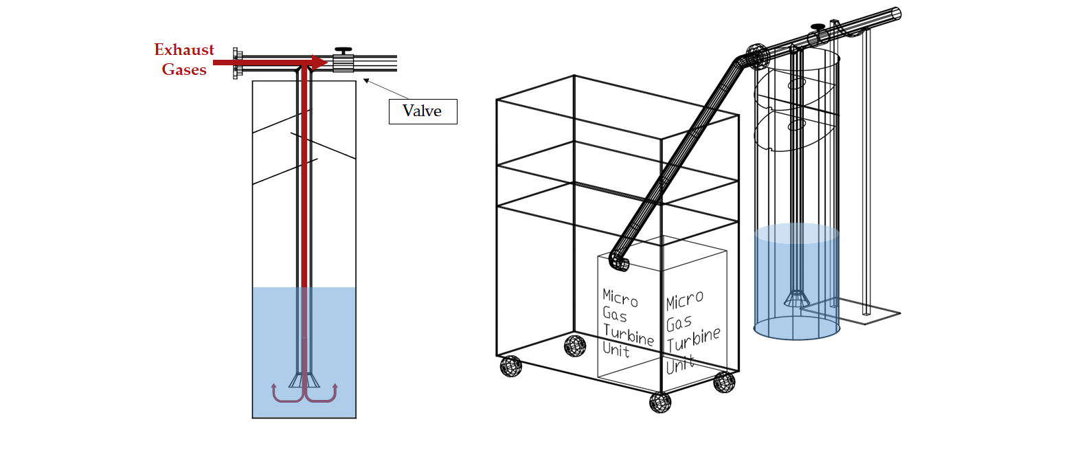
Figure 1
→ Tank.
The tank was made from a steel plate, which was bent to achieve a diameter of 400 mm and, subsequently, welded to make it watertight. The tank, which initially had both ends open, its bottom was been welded to another plate (in this case circular) with a diameter of 410 mm.

Figure 2
→ Piping.
The ducts through which the gases flow have been manufactured from two-inch steel pipes, which have been tailored cut and welded to achieve the desired geometry, with the aid of auxiliary elements such as elbows, flanges and bifurcations.
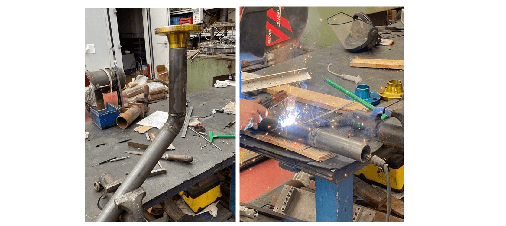
Figure 3
→ Difusser.
As verified by the hydraulic tests, the diffuser is perforated, in this case of 5 mm, all along its contour to achieve a correct system performance, using the column drill of the University of Seville facilities. The diffuser geometry is a standardised reduction from 4 inches to 2 inches in diameter.
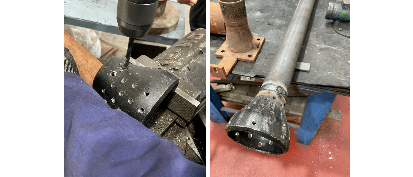
Figure 4
→ Baffles.
To avoid overly aggressive brine bubbling and possible leakages, three baffles are welded on the pipe where the gases flow down into the bulk, with an inclination of 12 degrees.
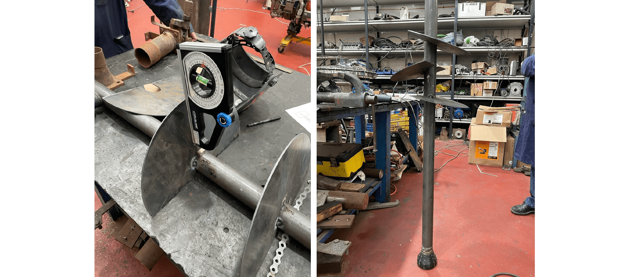
Figure 5
→ Thermal inslulation.
In order to reduce heat losses through the ZLD piping preventing an elevated temperature drop, the piping have been coated with a thermal insulation.
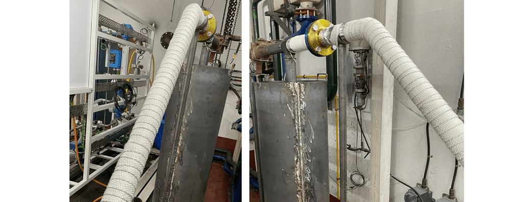
Figure 6


